Description
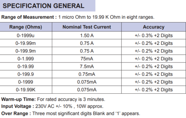
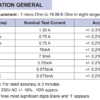
Range of Measurement: 1 micro Ohm to 19.99 K Ohm in eight ranges
Test Procedure
1. To Determine the Resistivity of Copper Wires.
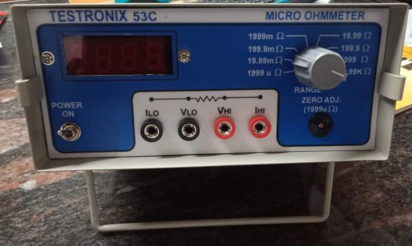
Zero Setting: Connect the test leads -V & +V only. Do not connect -I & +I leads. The selector switch should be in the 1999u Ohm position.
Switch ‘ON’ power and stabilize the instrument for 3 Minutes. Set Zero by zero setting knob. The best Zero setting is when the ‘-’ sign blinks.
During measurement, a zero setting may be made by removing the +I lead even while the other leads are connected to the unit under
test. Range of 199.9m Ohms and 19.99 Ohms do not need Zero setting and stabilization.
Connect sample conductor in 4 terminal connections as follows:

-I & +I = Current Leads , -V & +V =, Potential Leads.
L= the instrument indicates the resistance of the conductor in Length L, the distance between Potential leads should be kept at 1 meter for convenience. Keep current leads well away from potential leads.
Take care of that clip -I should NOT touch V &+V directly except through the conductor.
2. Measurement of Resistance of Transformers, Motors, etc.
Connect leads in 2 or 4 terminal arrangements. Switch ’ON’ power. Change range if Required. Wait for a few seconds for a stable
reading. Switch off power and disconnect leads and change over to the next measurement. Do not disconnect leads when the instrument
is ‘ON’.
3. Calculation of Heater Resistance.
V2/W = R…………………………………………….. where V = Heater operating voltage
W = Wattage of heater
R = Resistance of heater.
4. Measurement of Temperature Rise.
Of copper windings by an increase in resistance (IS-9678-1980).
T2 +235 R2
T1 +235 R1 where
T2 = Temperature in Deg. C of winding at the end of the test.
R2 = Resistance of winding at the end of the test.
T1 = Temperature in Deg. C of winding (cold) at the moment of initial resistance measurement, and
R1 = Initial resistance of the winding.
5. Instrument Adjustment & Calibration.
Test instruments required:
1. Std. 200mV DC meter of 4 ½ digit of known accuracy.
2 . Std. resistance of 1m Ohms,10m Ohms, 100m Ohms, 1 Ohm,10 Ohms, 1K Ohm & 10K Ohms
Procedure:
Connect 10 Ohms std resistor to the instrument. Switch ‘ON’ Power. Clip Std voltmeter across clips -V & +V. Adjust test current by
preset P5 so that Std Voltmeter reads 75mV. Adjust instruments indication by preset on DPM to read the value of std 10 Ohms resistor.
Change range to 1.999 Ohms, Connect 1 Ohm std resistor. Adjust test current by adjusting preset P4 so that the instrument
displays the value of std 1 Ohm resistor. Set all other ranges likewise. All ranges must be adjusted by connecting resistors in 4
Terminal connection. Please recheck calibration using the same resistors. Please send this manual with the instrument whenever
it is sent to a laboratory for re-calibration. Recommended re-calibration cycle is 1 Year.
6. Operational Safety.
Extreme care must be taken while calibrating the instrument as there are dangers of high voltage inside the instrument.


Reviews
There are no reviews yet.